How to Choose a Robot Arm for Your Factory: Payload, Reach, Repeatability
The robot arm catalogues all look the same after a while: shiny models, long spec tables, prices on request. But behind every good robotic investment is a shortlist built on three numbers — payload, reach, repeatability — plus a few constraints the datasheet does not headline. Here is how to read them, in the order that matters, and how to sanity-check your choice in CAD before you sign anything.
Start with the payload, but read the fine print
Payload is the maximum mass the arm can handle at full speed and full extension. It looks simple and it is not. Three things distort it:
- Payload is rated at the flange, not at the tool tip. Your gripper, sensor, and cabling all consume payload before the part does. A 10 kg arm with a 3 kg gripper really carries 7 kg.
- Payload falls with reach and speed. The same arm rated 10 kg at 1.2 m may drop to 4 kg at full extension, and less at high acceleration. The rated number is usually the best case.
- Dynamic loads matter. A part swung at speed exerts far more than its static weight at the wrist.
Rule of thumb: pick an arm rated for at least 1.5× your real part-plus-tooling mass. If your part plus gripper is 6 kg, an arm rated 10 kg is a comfortable floor.
Reach: measure the cell, not the brochure
Reach is the horizontal distance from the base axis to the flange at full extension. The mistake here is ordering reach for the part while forgetting the table, the fixture, and the guarding that sit between the base and the part.
Draw the cell: base position, part envelope, fixture, and the extremes you need to hit — the back corner of the fixture, the far pallet slot, the unload position. Your required reach is the distance to the furthest point, not to the part center. Add 10–15% margin, because the wrist has to orient the tool at that point, which shortens the effective reach.
Repeatability is about the process, not the part
Repeatability (typically ±0.02 to ±0.1 mm for industrial arms) tells you how precisely the arm returns to a taught position. It matters most for:
- Machine tending — placing parts into chucks and fixtures where the same insertion point repeats all day
- Pick-and-place at speed — where the arm must hit the same pickup point after thousands of cycles
- Welding and dispensing — where bead or seam position tolerances are tight
For general palletizing and rough handling, ±0.1 mm is plenty; paying extra for ±0.02 mm buys nothing you can use.
The constraints the datasheet hides
- Degrees of freedom. Six axes reach any orientation; four or five axes are cheaper and fine for straight-line transfer. Match axes to the job, not to the spec sheet.
- Mounting. Floor, wall, and ceiling mounts change the effective working envelope. A floor-mounted arm reaching over a tall fixture may need more reach than a ceiling mount would.
- Environment. Welding cells need foundry or IP67-rated versions; clean assembly needs different sealing. A standard arm near weld spatter will not last.
- Controller and safety. Check the controller's I/O, fieldbus support, and whether safety-rated features (safe stop, speed limits) are included or priced separately.
- End-effector integration. Verify the flange pattern matches your tooling, or budget an adapter. A model with a clear flange interface makes this a 10-minute check.
Validate the choice in CAD before you buy
Nothing exposes a bad robot choice faster than a layout drawing. Drop the arm model into your cell assembly and check: does the flange reach every pickup and drop point with the tool oriented correctly? Does the base mount on your table? Does the arm hit guarding or cable trays at any wrist angle?
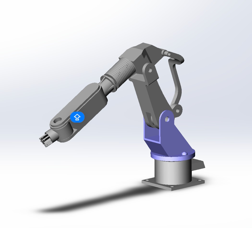
A dimensionally accurate industrial robot arm 3D model (STEP, SLDPRT, SLDASM) is exactly what you need for this check — it answers clearance, reach, and mounting questions against your real fixture geometry instead of against a brochure silhouette.
For linear-transfer applications — moving parts between stations in a straight line — a gantry robot pick-and-place cell is often a better fit than an articulated arm: cheaper, faster on long strokes, and the layout is simpler to guard. Model both options before deciding.
A shortlist in five steps
- [ ] 1. List your heaviest part + tooling, multiply by 1.5, and filter arms by that payload
- [ ] 2. Draw the cell and measure to the furthest point; add 10–15% for wrist orientation
- [ ] 3. Confirm repeatability against the process (tending/welding = tight; palletizing = loose)
- [ ] 4. Match axes, mounting, and environment rating to the job
- [ ] 5. Verify flange, reach, and clearances in CAD with a real model before quoting
The takeaway
Payload, reach, and repeatability narrow the field; the cell layout decides the winner. The shops that regret their robot purchase are almost always the ones that skipped the CAD check. The ones that model first end up with a machine that fits the cell, the process, and next year's jobs.
To start your layout check today, grab the Industrial Robotic Arm 3D Model ($50 indicative) — fully parametric in SolidWorks 2018+ with a clean feature tree. If your application needs a specific reach or a linear-transfer layout, tell us the cycle, the part, and the constraint and get a modeled solution built around them.